What Is A Non-Inverting Op-Amp?
- A non-inverting op-amp (operational amplifier) is a circuit that gives an output voltage in phase with the input voltage.
- The simple way to understand is, if the input pulse is positive, then the output is also positive.
- Now let’s understand the operation of the non-inverting amplifier below.
How Do Non-Inverting Op-Amps Work?
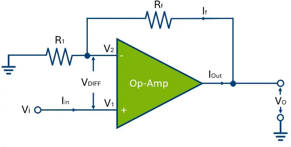
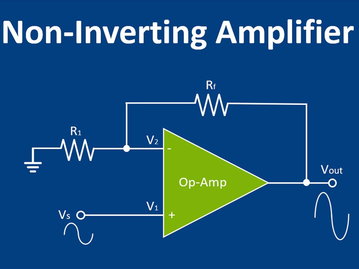
- Here the input signal which is to be amplified is applied to the non-inverting (+) terminal of the Op-Amp.
- The resistor R1 is connected to the inverting (-) pin of the opamp and the other terminal is connected to the ground and other resistor is the feedback resistor (Rf) is connected between the output and inverting (-) pins of the op-amp.
- The detailed connection diagram of the non-inverting amplifier is shown in Fig.

Non-Inverting Op-Amp Waveforms
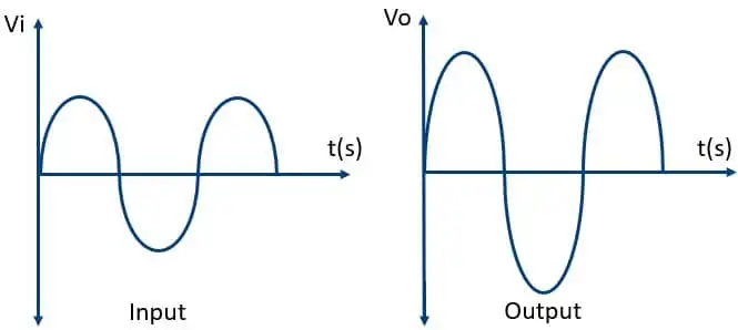
- The input and output waveforms of the non-inverting op-amp are shown in the below figure.
- These waveforms are created by assuming that the amplifier’s gain and a sine wave are used as input signals.
- From these waveforms, it’s evident that the output is twice the size of the input, like Vout = Av * Vin, and it is in phase to the input.

Expression For Closed-Loop Voltage Gain (Avf):
As we know for the ideal Op-Amp Input Impedance Ri=∞ there the current flowing from both input terminals is zero (I1 = I2 = 0).
From the above figure, we can write that,
$$V2\;=\;\frac{R1}{(Rf+R1)}\;*Vo$$
As per the virtual short concept
$$V2\;=\:Vs$$
$$Vs\;=\;\frac{R1}{(Rf+R1)}\;*Vo$$
$$Av\;=\;\frac{Vo}{Vs}\;=\;\frac{R1+Rf}{R1}$$
The final equation for the voltage gain of the inverting amplifier is,
$$Av\;=\;1+\frac{Rf}{R1}$$
Advantages
- It has a very high input impedance
- The gain factor is exceptionally high.
- The output of this op-amp is in phase with the input signal.
- Non-inverting op-amps generally do not attenuate the input signal, ensuring that the output signal retains its original magnitude.
- Non-inverting configurations are less sensitive to noise present in the input signal, resulting in an improved signal-to-noise ratio at the output.
Disadvantages
- Lower Voltage Gain compared to inverting configuration.
- Limited Common-Mode Rejection Ratio (CMRR).
- Susceptible to stability issues at high frequencies.
- May introduce phase shifts at high frequencies.

