What is an Inductor?
- An inductor is a passive electronic component that stores energy in a magnetic field when electrical current flows through it.
- It is a passive electrical component that opposes sudden changes in current. Inductors are also known as coils or chokes.
- The electrical symbol for an inductor is L.
- Inductors slow down current surges or spikes by temporarily storing energy in an electro-magnetic field and then releasing it back into the circuit.
Structure of an Inductor
An inductor typically consists of a coil of wire, often wound around a core made of magnetic material (like iron) or non-magnetic material (air core). The main parts of an inductor include:
- Coil (Winding): The wire, usually made of copper, is wound in a spiral or helical shape.
- Core: Inductors may have cores made of magnetic material to increase inductance. Air-core inductors are used where low inductance is sufficient.
- Terminals: These are the points where the inductor is connected to the circuit.

How does the inductor work?
- When an electrical current flows through the wire, it generates a magnetic field around it.
- The inductor resists changes in current due to the property called inductance.
- This behavior is governed by Faraday’s Law of Electromagnetic Induction, which states that a changing magnetic field will induce an electromotive force (EMF) in a conductor.
Key concepts:
- Inductance (L): The ability of an inductor to store energy in a magnetic field. It is measured in Henries (H).
- Magnetic Flux: The magnetic field lines generated around the coil.
Self-Inductance: When the magnetic field created by the current in the coil opposes changes in the current itself.
How Do Inductors Work in DC?
Inductors operate in the following manner when a DC source is connected to it:
- Initial Opposition to Current: When a DC voltage is first applied, the inductor resists the sudden change in current due to Lenz’s Law, causing a temporary voltage drop.
- Counter EMF Generation: As current starts flowing, the inductor produces a counter-electromotive force (EMF) that opposes the applied voltage.
- Gradual Current Increase: The current through the inductor rises gradually.
- Stable State Behavior: After sufficient time, the inductor effectively acts as a short circuit in the DC circuit, allowing current to flow without resistance.
- Magnetic Energy Storage: The inductor retains energy in the form of a magnetic field.
- Effect of Power Cutoff: If the DC supply is abruptly disconnected, the collapsing magnetic field induces a high-voltage spike, which can potentially harm circuit components.
- Role in Filtering: Inductors in DC circuits help smooth out fluctuations, making them useful for reducing ripple in power supplies.
How Do Inductors Work in AC?
Inductors when operated under conditions with an AC source behave in the following manner:
- Continuous Opposition to Current Change: In an AC circuit, the current direction changes periodically. The inductor continuously opposes these changes due to Lenz’s Law.
- Induced EMF in Every Cycle: As the AC current varies, the inductor generates a counter-electromotive force (EMF) that opposes the applied voltage in every cycle.
- Current Lagging Voltage: The current through an inductor lags the applied voltage by 90 degrees because the inductor resists immediate changes in current.
- Reactance Instead of Resistance: Instead of simple resistance, an inductor presents inductive reactance in AC circuits.
- Higher Frequency = More Opposition: As frequency increases, inductive reactance increases, making it harder for current to flow.
- Energy Storage and Release: The inductor alternately stores and releases energy in its magnetic field with each AC cycle.
- Use in Filtering and Tuning: Inductors are essential in AC circuits for applications like filters, resonant circuits, and transformers, where they help control frequency response and energy transfer.
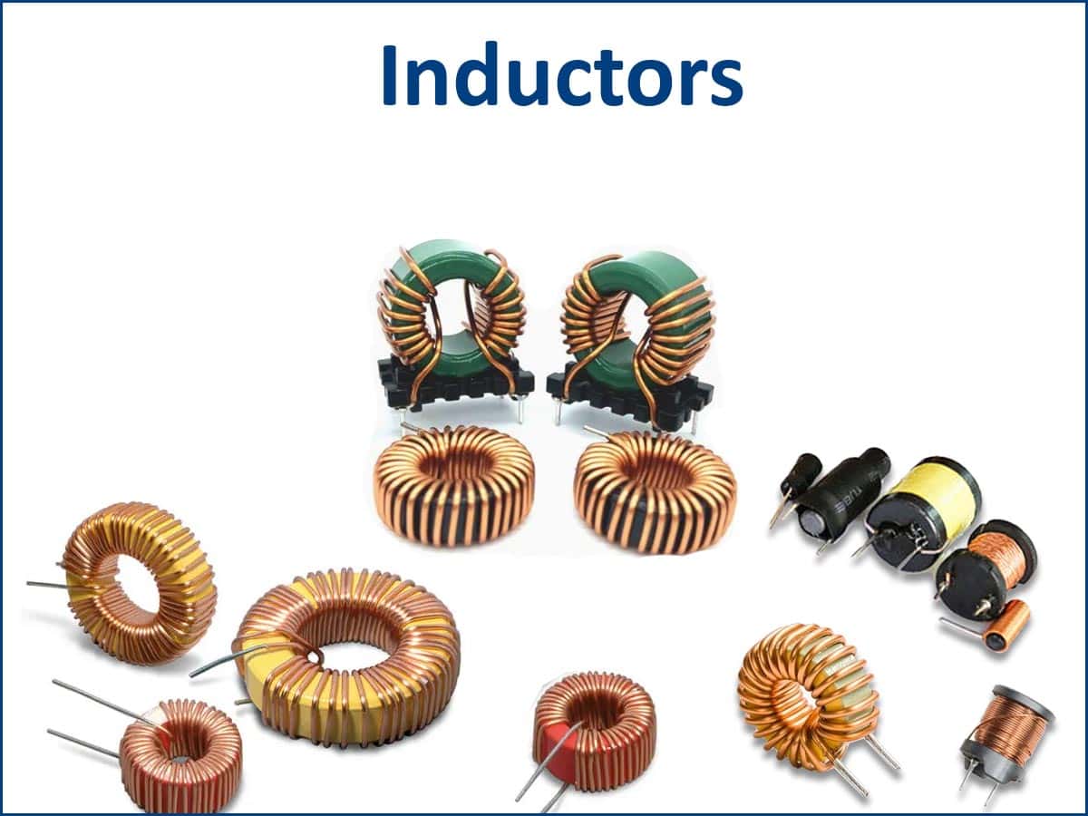
Types of Inductors:
Inductors come in various shapes, sizes, and configurations, depending on their application.
Air-Core Inductors:

- Air-core inductors use air or non-magnetic materials as their core, resulting in lower inductance but eliminating core saturation and hysteresis losses.
- They are highly efficient at high frequencies, making them ideal for RF and microwave applications.
- Since they do not suffer from eddy current losses, they offer stable performance across varying temperatures and frequencies.
- However, to achieve higher inductance, they require more turns of wire, making them larger in size.
Iron-Core Inductors:

- Iron-core inductors use a ferromagnetic core (such as iron or laminated steel) to increase inductance by concentrating the magnetic field.
- They provide higher inductance and better energy storage, making them ideal for low-frequency applications like power supplies and transformers.
- However, they suffer from hysteresis and eddy current losses, which can cause energy dissipation as heat.
- Despite these losses, they are widely used in power electronics where size and efficiency are crucial.
Ferrite-Core Inductors:

- Ferrite-core inductors use a ferrite material as the core, which is a ceramic compound of iron oxide mixed with other metals.
- They offer high inductance with low eddy current losses, making them ideal for high-frequency applications such as RF circuits, power supplies, and EMI suppression.
- Due to their high resistivity, they minimize energy losses, improving efficiency in switching power supplies.
- However, they can suffer from core saturation at high currents, which must be considered in power applications.
Toroidal Inductors:

- Toroidal inductors have a doughnut-shaped (toroidal) core, which helps contain the magnetic field within the core, reducing electromagnetic interference (EMI).
- They offer high inductance and efficiency while minimizing energy losses due to their closed-loop magnetic path.
- Commonly made from iron powder or ferrite, they are used in power supplies, transformers, and RF applications.
- Although they provide excellent performance, their winding process is more complex, making them harder to manufacture compared to solenoid inductors.
Multilayer Inductors:

- Multilayer inductors consist of multiple layers of conductive coils embedded in a ceramic or ferrite material, providing compact size and high inductance.
- They are commonly used in high-frequency applications, such as RF circuits, signal processing, and EMI filtering.
- Due to their low DC resistance (DCR) and high self-resonant frequency (SRF), they offer efficient performance in miniaturized electronic devices.
- However, their inductance is fixed and limited, making them less flexible than wire-wound inductors.
Inductive Resistance:
Inductors resist changes in current. This property is quantified as inductive reactance (XL), which increases with frequency. Inductive reactance is given by:
XL=2πfL
Where:
- XL= Inductive Reactance (in Ohms)
- f= Frequency of the AC signal (in Hertz)
- L= Inductance (in Henries)
At high frequencies, the reactance becomes significant, making inductors effective for high-frequency filtering.
Applications of Inductors:
- Power Supplies: Inductors store energy and help regulate voltage in power converters and filters.
- Radio-Frequency Circuits: Inductors are critical in tuning circuits, such as radio receivers and transmitters.
- Transformers: Two inductors wound on a shared core transfer electrical energy between circuits.
- Motors and Generators: Inductors play a key role in generating electromagnetic fields that convert electrical energy to mechanical energy, and vice versa.
- EMI Filters: Inductors are used to reduce electromagnetic interference in sensitive circuits.